Design for Resilience
As a part of system design, “resilience” describes the system’s ability to hold out against a major malfunction or disruption. Resilient systems can recover automatically from failures in parts of the system—or possibly the failure of the entire system—and return to normal operations after the problems are addressed. Services in a resilient system ideally remain running throughout an incident, perhaps in a degraded mode. Designing resilience into every layer of a system’s design helps defend that system against unanticipated failures and attack scenarios.
Designing a system for resilience is different from designing for recovery (covered in depth in Chapter 9). Resilience is closely tied to recovery, but while recovery focuses on the ability to fix systems after they break, resilience is about designing systems that delay or withstand breakage. Systems designed with a focus on both resilience and recovery are better able to recover from failures, and require minimal human intervention.
Design Principles for Resilience
A system’s resilience properties are built on the design principles discussed earlier in Part II. In order to evaluate a system’s resilience, you must have a good understanding of how that system is designed and built. You need to align closely with other design qualities covered in this book—least privilege, understandability, adaptability, and recovery—to strengthen your system’s stability and resilience attributes.
The following approaches, each of which this chapter explores in depth, characterize a resilient system:
Design each layer in the system to be independently resilient. This approach builds defense in depth with each layer.
Prioritize each feature and calculate its cost, so you understand which features are critical enough to attempt to sustain no matter how much load the system experiences, and which features are less important and can be throttled or disabled when problems arise or resources are constrained. You can then determine where to apply the system’s limited resources most effectively, and how to maximize the system’s serving capabilities.
Compartmentalize the system along clearly defined boundaries to promote the independence of the isolated functional parts. This way, it’s also easier to build complementary defense behaviors.
Use compartment redundancy to defend against localized failures. For global failures, have some compartments provide different reliability and security properties.
Reduce system reaction time by automating as many of your resilience measures as you can safely. Work to discover new failure modes that could benefit either from new automation or improvements to existing automation.
Maintain the effectiveness of the system by validating its resilience properties—both its automated response and any other resilience attributes of the system.
Defense in Depth
Defense in depth protects systems by establishing multiple layers of defense perimeters. As a result, attackers have limited visibility into the systems, and successful exploits are harder to launch.
The Trojan Horse
The story of the Trojan Horse, as told by Virgil in the Aeneid, is a cautionary tale about the dangers of an inadequate defense. After 10 fruitless years besieging the city of Troy, the Greek army constructs a large wooden horse that it presents as a gift to the Trojans. The horse is brought within the walls of Troy, and attackers hiding inside the horse burst forth, exploit the city’s defenses from the inside, and then open the city gates to the entire Greek army, which destroys the city.
Imagine this story’s ending if the city had planned for defense in depth. First, Troy’s defensive forces might have inspected the Trojan Horse more closely and discovered the deception. If the attackers had managed to make it inside the city gates, they could have been confronted with another layer of defense—for example, the horse might have been enclosed in a secure courtyard, with no access to the rest of the city.
What does a 3,000-year-old story tell us about security at scale, or even security itself? First, if you’re trying to understand the strategies you need to defend and contain a system, you must first understand the attack itself. If we consider the city of Troy as a system, we can walk through the attackers’ steps (stages of the attack) to uncover weaknesses that defense in depth might address.
At a high level, we can divide the Trojan attack into four stages:
Threat modeling and vulnerability discovery—Assess the target and specifically look for defenses and weaknesses. The attackers couldn’t open the city gates from the outside, but could they open them from the inside?
Deployment—Set up the conditions for the attack. The attackers constructed and delivered an object that Troy eventually brought inside its city walls.
Execution—Carry out the actual attack, which capitalizes on the previous stages. Soldiers came out of the Trojan Horse and opened the city gates to let in the Greek army.
Compromise—After successful execution of the attack, the damage occurs and mitigation begins.
The Trojans had opportunities to disrupt the attack at every stage before the compromise, and paid a heavy price for missing them. In the same way, your system’s defense in depth can reduce the price you might have to pay if your system is ever compromised.
Threat modeling and vulnerability discovery
Attackers and defenders can both assess a target for weaknesses. Attackers perform reconnaissance against their targets, find weaknesses, and then model attacks. Defenders should do what they can to limit the information exposed to attackers during reconnaissance. But because defenders can’t completely prevent this reconnaissance, they must detect it and use it as a signal. In the case of the Trojan Horse, the defenders might have been on the alert because of inquiries from strangers about how the gates were defended. In light of that suspicious activity, they would have then exercised extra caution when they found a large wooden horse at the city gate.
Making note of these strangers’ inquiries amounts to gathering intelligence on threats. There are many ways to do this for your own systems, and you can even choose to outsource some of them. For example, you might do the following:
Monitor your system for port and application scans.
Keep track of DNS registrations of URLs similar to yours—an attacker might use those registrations for spear phishing attacks.
Buy threat intelligence data.
Build a threat intelligence team to study and passively monitor the activities of known and likely threats to your infrastructure. While we don’t recommend that small companies invest resources in this approach, it may become cost-effective as your company grows.
As a defender with inside knowledge of your system, your assessment can be more detailed than the attacker’s reconnaissance. This is a critical point: if you understand your system’s weaknesses, you can defend against them more efficiently. And the more you understand the methods that attackers are currently using or are capable of exploiting, the more you amplify this effect. A word of caution: beware of developing blind spots to attack vectors you consider unlikely or irrelevant.
Deployment of the attack
If you know that attackers are performing reconnaissance against your system, efforts to detect and stop the attack are critical. Imagine that the Trojans had decided not to permit the wooden horse to enter the city gates because it was created by someone they did not trust. Instead, they might have thoroughly inspected the Trojan Horse before allowing it inside, or perhaps they might have just set it on fire.
In modern times, you can detect potential attacks using network traffic inspection, virus detection, software execution control, protected sandboxes,1 and proper provisioning of privileges for signaling anomalous use.
Execution of the attack
If you can’t prevent all deployments from adversaries, you need to limit the blast radius of potential attacks. If the defenders had boxed in the Trojan Horse, thereby limiting their exposure, the attackers would have had a much harder time advancing from their hiding spot unnoticed. Cyberwarfare refers to this tactic (described in more detail in Runtime layers) as sandboxing.
Compromise
When the Trojans woke to find their enemies standing over their beds, they knew their city had been compromised. This awareness came well after the actual compromise occurred. Many unfortunate banks faced a similar situation in 2018 after their infrastructure was polluted by EternalBlue and WannaCry.
How you respond from this point forward determines how long your infrastructure remains compromised.
Google App Engine Analysis
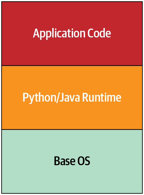
Let’s consider defense in depth as applied to a more modern case: Google App Engine. Google App Engine allows users to host application code, and to scale as load increases without managing networks, machines, and operating systems. Figure 8-1 shows a simplified architecture diagram of App Engine in its early days. Securing the application code is a developer’s responsibility, while securing the Python/Java runtime and the base OS is Google’s responsibility.
The original implementation of Google App Engine required special process isolation considerations. At that time Google used traditional POSIX user isolation as its default strategy (through distinct user processes), but we decided that running each user’s code in an independent virtual machine was too inefficient for the level of planned adoption. We needed to figure out how to run third-party, untrusted code in the same way as any other job within Google’s infrastructure.
Risky APIs
Initial threat modeling for App Engine turned up a few worrisome areas:
Network access was problematic. Up to that point, all applications running within the Google production network were assumed to be trusted and authenticated infrastructure components. Since we were introducing arbitrary, untrusted third-party code into this environment, we needed a strategy to isolate internal APIs and network exposure from App Engine. We also needed to bear in mind that App Engine itself was running on that same infrastructure, and therefore was dependent on access to those same APIs.
The machines running user code required access to the local filesystem. At least this access was limited to the directories belonging to the given user, which helped protect the execution environment and reduce the risk of user-provided applications interfering with applications of other users on the same machine.
The Linux kernel meant that App Engine was exposed to a large attack surface, which we wanted to minimize. For example, we wanted to prevent as many classes of local privilege escalation as possible.
To address these challenges, we first examined limiting user access to each API. Our team removed built-in APIs for I/O operations for networking and filesystem interactions at runtime. We replaced the built-in APIs with “safe” versions that made calls to other cloud infrastructure, rather than directly manipulating the runtime environment.
To prevent users from reintroducing the intentionally removed capabilities to the interpreters, we didn’t allow user-supplied compiled bytecode or shared libraries. Users had to depend on the methods and libraries we provided, in addition to a variety of permitted runtime-only open source implementations that they might need.
Runtime layers
We also extensively audited the runtime base data object implementations for features that were likely to produce memory corruption bugs. This audit produced a handful of upstream bug fixes in each of the runtime environments we launched.
We assumed that at least some of these defensive measures would fail, as we weren’t likely to find and predict every exploitable condition in the chosen runtimes. We decided to specifically adapt the Python runtime to compile down to Native Client (NaCL) bitcode. NaCL allowed us to prevent many classes of memory corruption and control-flow subversion attacks that our in-depth code auditing and hardening missed.
We weren’t completely satisfied that NaCL would contain all risky code breakouts and bugs in their entirety, so we added a second layer of ptrace sandboxing to filter and alert on unexpected system calls and parameters. Any violations of these expectations immediately terminated the runtime and dispatched alerts at high priority, along with logs of relevant activity.
Over the next five years, the team caught a few cases of anomalous activity resulting from exploitable conditions in one of the runtimes. In each case, our sandbox layer gave us a significant advantage over attackers (whom we confirmed to be security researchers), and our multiple layers of sandboxing contained their activities within the design parameters.
Functionally, the Python implementation in App Engine featured the sandboxing layers shown in Figure 8-2.
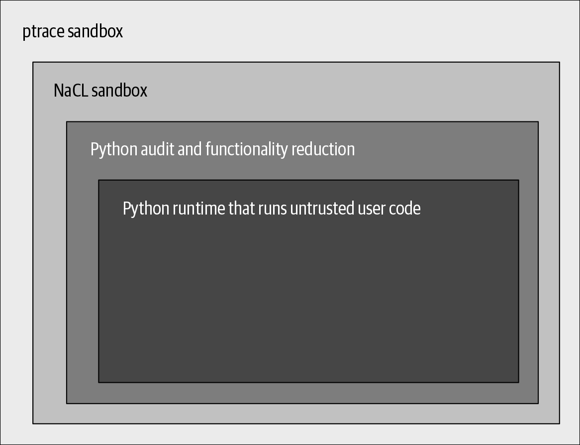
App Engine’s layers are complementary, with each layer anticipating the weak points or likely failures of the previous one. As defense activations move through the layers, signals of a compromise become stronger, allowing us to focus efforts on probable attacks.
Although we took a thorough and layered approach to security for Google App Engine, we still benefited from external help in securing the environment.2 In addition to our team finding anomalous activity, external researchers discovered several cases of exploitable vectors. We’re grateful to the researchers who found and disclosed the gaps .
Controlling Degradation
When designing for defense in depth, we assume that system components or even entire systems can fail. Failures can happen for many reasons, including physical damage, a hardware or network malfunction, a software misconfiguration or bug, or a security compromise. When a component fails, the impact may extend to every system that depends on it. The global pool of similar resources also becomes smaller—for example, disk failures reduce overall storage capacity, network failures reduce bandwidth and increase latency, and software failures reduce the computational capacity system-wide. The failures might compound—for example, a storage shortage could lead to software failures.
Resource shortages like these, or a sudden spike in incoming requests like those caused by the Slashdot effect, misconfiguration, or a denial-of-service attack, could lead to system overload. When a system’s load exceeds its capacity, its response inevitably begins to degrade, and that can lead to a completely broken system with no availability. Unless you’ve planned for this scenario in advance, you don’t know where the system may break—but this will most likely be where the system is weakest, and not where it’s safest.
To control degradation, you must select which system properties to disable or adjust when dire circumstances arise, while doing all you can to protect the system’s security. If you deliberately design multiple response options for circumstances like these, the system can make use of controlled breakpoints, rather than experiencing a chaotic collapse. Instead of setting off cascading failures and dealing with the disorder that follows, your system can respond by degrading gracefully. Here are some ways you can make that happen:
Free up resources and decrease the rate of failed operations by disabling infrequently used features, the least critical functions, or high-cost service capabilities. You can then apply the freed resources to preserving important features and functions. For example, most systems that accept TLS connections support both Elliptic Curve (ECC) and RSA cryptosystems. Depending on your system’s implementation, one of the two will be cheaper while giving you comparable security. In software, ECC is less resource-intensive for private key operations.3 Disabling support for RSA when systems are resource-constrained will make room for more connections at the lower cost of ECC.
Aim for system response measures to take effect quickly and automatically. This is easiest with servers under your direct control, where you can arbitrarily toggle operational parameters of any scope or granularity. User clients are harder to control: they have long rollout cycles because client devices may postpone or be unable to receive updates. Additionally, the diversity of client platforms increases the chance of rollbacks of response measures due to unanticipated incompatibilities.
Understand which systems are critical for your company’s mission as well as their relative importance and interdependencies. You might have to preserve the minimal features of these systems in proportion to their relative value. For example, Google’s Gmail has a “simple HTML mode” that disables fancy UI styling and search autocompletion but allows users to continue opening mail messages. Network failures limiting bandwidth in a region could deprioritize even this mode if that allowed network security monitoring to continue to defend user data in the region.
If these adjustments meaningfully improve the system’s capacity to absorb load or failure, they provide a critical complement to all other resilience mechanisms—and give incident responders more time to respond. It’s better to make the essential and difficult choices in advance rather than when under pressure during an incident. Once individual systems develop a clear degradation strategy, it becomes easier to prioritize degradation at a larger scope, across multiple systems or product areas.
Differentiate Costs of Failures
There is some cost to any failed operation—for example, a failed data upload from a mobile device to an application backend consumes computing resources and network bandwidth to set up an RPC and push some data. If you can refactor your flows to fail early or cheaply, you may be able to reduce or avoid some failure-related waste.
To reason about cost of failures:
- Identify the total costs of individual operations.
- For example, you could collect CPU, memory, or bandwidth impact metrics during load testing of a particular API. Focus first on the most impactful operations—either by criticality or frequency—if pressed for time.
- Determine at what stage in the operation these costs are incurred.
- You could inspect source code or use developer tools to collect introspection data (for example, web browsers offer tracking of request stages). You could even instrument the code with failure simulations at different stages.
Armed with the information you gather about operation costs and failure points, you can look for changes that could defer higher-cost operations until the system progresses further toward success.
Computing resources
The computing resources that a failing operation consumes—from the beginning of the operation until failure—are unavailable to any other operations. This effect multiplies if clients retry aggressively on failure, a scenario that might even lead to a cascading system failure. You can free up computing resources more quickly by checking for error conditions earlier in the execution flows—for example, you can check the validity of data access requests before the system allocates memory or initiates data reads/writes. SYN cookies can let you avoid allocating memory to TCP connection requests originating from spoofed IP addresses. CAPTCHA can help to protect the most expensive operations from automated abuse.
More broadly, if a server can learn that its health is declining (for example, from a monitoring system’s signals), you can have the server switch into a lame-duck mode:4 it continues to serve, but lets its callers know to throttle down or stop sending requests. This approach provides better signals to which the overall environment can adapt, and simultaneously minimizes resources diverted to serving errors.
It’s also possible for multiple instances of a server to become unused because of external factors. For example, the services they run could be “drained” or isolated because of a security compromise. If you monitor for such conditions, the server resources could be temporarily released for reuse by other services. Before you reallocate resources, however, you should be certain to secure any data that can be helpful for a forensic investigation.
User experience
The system’s interactions with the user should have an acceptable level of behavior in degraded conditions. An ideal system informs users that its services might be malfunctioning, but lets them continue to interact with parts that remain functional. Systems might try different connection, authentication, and authorization protocols or endpoints to preserve the functional state. Any data staleness or security risks due to failures should be clearly communicated to the users. Features that are no longer safe to use should be explicitly disabled.
For example, adding an offline mode to an online collaboration application can preserve core functionality despite temporary loss of online storage, the ability to show updates from others, or integration with chat features. In a chat application with end-to-end encryption, users might occasionally change their encryption key used for protecting communications. Such an application would keep all previous communications accessible, because their authenticity is not affected by this change.
In contrast, an example of a poor design would be a situation where the entire GUI becomes unresponsive because one of its RPCs to a backend has timed out. Imagine a mobile application designed to connect to its backends on startup in order to display only the freshest content. The backends could be unreachable simply because the device’s user disabled the connectivity intentionally; still, users would not see even the previously cached data.
A user experience (UX) research and design effort may be required to arrive at a UX solution that delivers usability and productivity in a degraded mode.
Speed of mitigation
The recovery speed of a system after it fails affects the cost of that failure. This response time includes the time between when a human or automation makes a mitigating change and when the last affected instance of the component is updated and recovers. Avoid placing critical points of failure into components like client applications, which are harder to control.
Going back to the earlier example of the mobile application that initiates a freshness update on launch, that design choice turns connectivity to the backends into a critical dependency. In this situation, the initial problems are amplified by the slow and uncontrollable rate of application updates.
Deploy Response Mechanisms
Ideally, a system should actively respond to deteriorating conditions with safe, preprogrammed measures that maximize the effectiveness of the response while minimizing risks to security and reliability. Automated measures can generally perform better than humans—humans are slower to respond, may not have sufficient network or security access to complete a necessary operation, and aren’t as good at solving for multiple variables. However, humans should remain in the loop to provide checks and balances, and to make decisions under unforeseen or nontrivial circumstances.
Let’s consider in detail managing excessive load—whether due to loss of serving capacity, benign traffic spikes, or even DoS attacks. Humans might not respond fast enough, and traffic could overwhelm servers enough to lead to cascading failures and an eventual global service crash. Creating a safeguard by permanently overprovisioning servers wastes money and doesn’t guarantee a safe response. Instead, servers should adjust how they respond to load based upon current conditions. You can use two specific automation strategies here:
Load shedding is done by returning errors rather than serving requests.
Throttling of clients is done by delaying responses until closer to the request deadline.
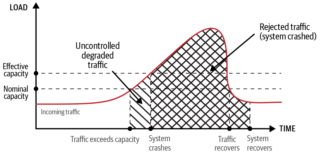
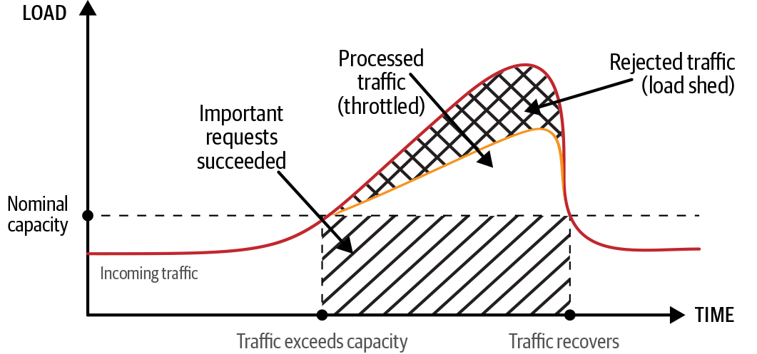
Figure 8-3 illustrates a traffic spike that exceeds the capacity. Figure 8-4 illustrates the effects of load shedding and throttling to manage the load spike. Note the following:
The curve represents requests per second, and the area under it represents total requests.
Whitespace represents traffic processed without failure.
The backward-slashed area represents degraded traffic (some requests failed).
The crosshatched areas represent rejected traffic (all requests failed).
The forward-slashed area represents traffic subject to prioritization (important requests succeeded).
Figure 8-3 shows how the system might actually crash, leading to a greater impact in terms of both volume (number of requests lost) and time (duration of the outage extends past the traffic spike). Figure 8-3 also distinguishes the uncontrolled nature of degraded traffic (the backward-slashed area) prior to system crash. Figure 8-4 shows that the system with load shedding rejects significantly less traffic than in Figure 8-3 (the crosshatched area), with the rest of the traffic either processed without failure (whitespace area) or rejected if lower priority (forward-slashed area).
Load shedding
The primary resilience objective of load shedding (described in Chapter 22 of the SRE book) is to stabilize components at maximum load, which can be especially beneficial for preserving security-critical functions. When the load on a component starts to exceed its capacity, you want the component to serve errors for all excessive requests rather than crashing. Crashing makes all of the component’s capacity unavailable—not just the capacity for the excess requests. When this capacity is gone, the load just shifts elsewhere, possibly causing a cascading failure.
Load shedding allows you to free server resources even before a server’s load reaches capacity, and to make those resources available for more valuable work. To select which requests to shed, the server needs to have notions of request priority and request cost. You can define a policy that determines how many of each request type to shed based upon request priority, request cost, and current server utilization. Assign request priorities based on the business criticality of the request or its dependents (security-critical functions should get high priority). You can either measure or empirically estimate request costs.5 Either way, these measurements should be comparable to server utilization measurements, such as CPU and (possibly) memory usage. Computing request costs should of course be economical.
Throttling
Throttling (described in Chapter 21 of the SRE book) indirectly modifies the client’s behavior by delaying the present operation in order to postpone future operations. After the server receives a request, it may wait before processing the request or, once it has finished processing the request, wait before sending the response to the client. This approach reduces the rate of requests the server receives from clients (if clients send requests sequentially), which means that you can redirect the resources saved during wait times.
Similar to load shedding, you could define policies to apply throttling to specific offending clients, or more generally to all clients. Request priority and cost play a role in selecting which requests to throttle.
Automated response
Server utilization statistics can help determine when to consider applying controls like load shedding and throttling. The more heavily a server is loaded, the less traffic or load it can handle. If controls take too long to activate, higher-priority requests may end up being dropped or throttled.
To effectively manage these degradation controls at scale, you may need a central internal service. You can translate business considerations about mission-critical features and the costs of failure into policies and signals for this service. This internal service can also aggregate heuristics about clients and services in order to distribute updated policies to all servers in near real time. Servers can then apply these policies according to rules based on server utilization.
Some possibilities for automated response include the following:
Implementing load-balancing systems that can respond to throttling signals and attempt to shift traffic to servers with lower loads
Providing DoS protections that can assist in response to malicious clients if throttling is ineffective or damaging
Using reports of heavy load shedding for critical services to set off preparation for failover to alternative components (a strategy that we discuss later in this chapter)
You can also use automation for self-reliant failure detection: a server that determines that it can’t serve some or all classes of requests can degrade itself to a full load-shedding mode. Self-contained or self-hosted detection is desirable because you don’t want to rely on external signals (possibly simulated by an attacker) to force an entire fleet of servers into an outage.
As you implement graceful degradation, it’s important to determine and record levels of system degradation, regardless of what set off the problem. This information is useful for diagnosing and debugging. Reporting the actual load shedding or throttling (whether self-imposed or directed) can help you evaluate global health and capacity and detect bugs or attacks. You also need this information in order to evaluate the current remaining system capacity and user impact. In other words, you want to know how degraded the individual components and the entire system are, and what manual actions you might need to take. After the event, you’ll want to evaluate the effectiveness of your degradation mechanisms.
Automate Responsibly
Exercise caution when creating automated response mechanisms so that they do not degrade system security and reliability to an unintended degree.
Failing safe versus failing secure
When designing a system to handle failure, you must balance between optimizing for reliability by failing open (safe) and optimizing for security by failing closed (secure):6
To maximize reliability, a system should resist failures and serve as much as possible in the face of uncertainty. Even if the system’s integrity is not intact, as long as its configuration is viable, a system optimized for availability will serve what it can. If ACLs failed to load, the assumed default ACL is “allow all.”
To maximize security, a system should lock down fully in the face of uncertainty. If the system cannot verify its integrity—regardless of whether a failed disk took away a part of its configs or an attacker changed the configs for an exploit—it can’t be trusted to operate and should protect itself as much as possible. If ACLs failed to load, the assumed default ACL is “deny all.”
These principles of reliability and security are clearly at odds. To resolve this tension, each organization must first determine its minimal nonnegotiable security posture, and then find ways to provide the required reliability of critical features of security services. For example, a network configured to drop low-QoS (quality of service) packets might require that security-oriented RPC traffic be tagged for special QoS to prevent packet drops. Security-oriented RPC servers might need special tagging to avoid CPU starvation by workload schedulers.
A foothold for humans
Sometimes humans must get involved in service degradation decisions. For example, the ability of rule-based systems to make a judgment call is inherently limited by predefined rules. Automation doesn’t act when faced with unforeseen circumstances that don’t map to any of the system’s predefined responses. An automated response might also produce unforeseen circumstances due to a programming error. Allowing appropriate human intervention to deal with these and similar situations requires some forethought in system design.
First, you should prevent automation from disabling the services that employees use to recover your infrastructure (see Emergency Access). It’s important to design protections for these systems so that even DoS attacks cannot completely prevent access. For example, a SYN attack must not stop a responder from opening a TCP connection for an SSH session. Be sure to implement low-dependency alternatives, and continuously validate the capabilities of those alternatives.
In addition, don’t allow automation to make unsupervised policy changes of either large magnitude (for example, a single server shedding all RPCs) or substantial scope (all servers shedding some RPC). Consider implementing a change budget instead. When automation exhausts that budget, no automatic refresh occurs. Instead, a human must increase the budget or make a different judgment call. Note that despite this human intervention, automation is still in place .
Controlling the Blast Radius
You can add another layer to your defense-in-depth strategy by limiting the scope of each part of your system. For example, consider network segmentation. In the past, it was common for an organization to have a single network that contained all of its resources (machines, printers, storage, databases, and so on). These resources were visible to any user or service on that network, and access was controlled by the resource itself.
Today, a common way to improve security is to segment your network and grant access to each segment to specific classes of users and services. You can do this by using virtual LANs (VLANs) with network ACLs, which is an easy-to-configure, industry-standard solution. You can control traffic into each segment, and control which segments are allowed to communicate. You can also limit each segment’s access to “need to know” information.
Network segmentation is a good example of the general idea of compartmentalization, which we discussed in Chapter 6. Compartmentalization involves deliberately creating small individual operational units (compartments) and limiting access to and from each one. It’s a good idea to compartmentalize most aspects of your systems—servers, applications, storage, and so on. When you use a single-network setup, an attacker who compromises a user’s credentials can potentially access every device on the network. When you use compartmentalization, however, a security breach or traffic overload in one compartment does not jeopardize all of the compartments.
Controlling the blast radius means compartmentalizing the impact of an event, similar to the way compartments on a ship grant resilience against the whole ship sinking. Designing for resilience, you should create compartmental barriers that constrain both attackers and accidental failures. These barriers allow you to better tailor and automate your responses. You can also use these boundaries to create failure domains that deliver component redundancy and failure isolation, as discussed in Failure Domains and Redundancies.
Compartments also aid in quarantine efforts, reducing the need for responders to actively balance defending and preserving evidence. Some compartments can be isolated and frozen for analysis while other compartments are recovered. Additionally, compartments create natural boundaries for replacement and repair during incident response—a compartment may be jettisoned to save the remainder of the system.
To control the blast radius of an incursion, you must have a way to establish boundaries and to be sure those boundaries are secure. Consider a job running in production as one compartment.7 This job must permit some access (you want the compartment to be useful), but not unrestricted access (you want to protect the compartment). Restricting who can access the job relies on your ability to recognize endpoints in production and confirm their identity.
You can do this by using authenticated remote procedure calls, which identify both parties within one connection. To protect the parties’ identities from spoofing and to conceal their contents from the network, these RPCs use mutually authenticated connections, which can certify the identities of both parties connected to the service. To permit endpoints to make more informed decisions about other compartments, you may add additional information that endpoints publish along with their identity. For example, you can add location information to the certificate so that you can reject nonlocal requests.
Once mechanisms to establish compartments are in place, you face a difficult tradeoff: you need to constrain your operations with enough separation to deliver useful-sized compartments, but without creating too much separation. For example, one balanced approach to compartmentalization would be to consider every RPC method as a separate compartment. This aligns compartments along logical application boundaries, and the count of compartments is linear to the number of system features.
Compartment separation that controls the acceptable parameter values of RPC methods would warrant more careful consideration. While this would create tighter security controls, the number of possible violations per RPC method is proportional to the number of RPC clients. This complexity would compound across all of the system’s features, and require coordination of changes in client code and server policy. On the other hand, compartments that wrap an entire server (regardless of its RPC services or their methods) are much easier to manage, but provide comparatively much less value. When balancing this tradeoff, it’s necessary to consult with the incident management and operations teams to consider your choices of compartment types and to validate the utility of your choices.
Imperfect compartments that don’t perfectly cover all edge cases can also provide value. For example, the process of finding the edge cases may cause an attacker to make a mistake that alerts you to their presence. Any time that it takes such an adversary to escape a compartment is additional time that your incident response team has to react.
Incident management teams must plan and practice tactics for sealing compartments to contain an incursion or a bad actor. Turning off part of your production environment is a dramatic step. Well-designed compartments give incident management teams the option to perform actions that are proportional to the incidents, so they don’t necessarily have to take an entire system offline.
When you implement compartmentalization, you face a tradeoff between having all customers share a single instance of a given service,8 or running separate service instances that support individual customers or subsets of customers.
For example, running two virtual machines (VMs)—each controlled by different mutually distrustful entities—on the same hardware comes with a certain risk: exposure to zero-day vulnerabilities in the virtualization layer perhaps, or subtle cross-VM information leaks. Some customers may choose to eliminate these risks by compartmentalizing their deployments based on physical hardware. To facilitate this approach, many cloud providers offer deployment on per-customer dedicated hardware.9 In this case, the cost of reduced resource utilization is reflected in a pricing premium.
Compartment separation adds resilience to a system as long as the system has mechanisms to maintain the separation. The difficult task is tracking those mechanisms and ensuring they remain in place. To prevent regressions, it’s valuable to validate that operations prohibited across separation boundaries indeed fail (see Continuous Validation). Conveniently, because operational redundancy relies on compartmentalization (covered in Failure Domains and Redundancies), your validation mechanisms can cover both prohibited and expected operations.
Google compartmentalizes by role, location, and time. When an attacker tries to compromise a compartmentalized system, the potential scope of any single attack is greatly reduced. If the system is compromised, the incident management teams have options to disable only parts of it to purge the effects of the compromise while leaving other parts operational. The following sections explore the different types of compartmentalization in detail.
Role Separation
Most modern microservices architecture systems allow users to run jobs as particular roles, sometimes referred to as service accounts. The jobs are then provided with credentials that allow them to authenticate to other microservices on the network in their specific roles. If an adversary compromises a single job, they will be able to impersonate the job’s corresponding role across the network. Because this allows the adversary to access all data that the other jobs running as that role could access, this effectively means that adversary has compromised the other jobs as well.
To limit the blast radius of such a compromise, different jobs should typically be run as different roles. For example, if you have two microservices that need access to two different classes of data (say, photos and text chats), running these two microservices as different roles can increase the resilience of your system even if the two microservices are developed and run by the same team.
Location Separation
Location separation helps to limit an attacker’s impact along an additional dimension: the location where the microservice is running. For example, you might want to prevent an adversary who has physically compromised a single datacenter from being able to read data in all your other datacenters. Similarly, you might want your most powerful administrative users to have their access permissions limited to only specific regions to mitigate insider risk.
The most obvious way to achieve location separation is to run the same microservices as different roles in different locations (like datacenters or cloud regions, which also typically correspond to different physical locations). You can then use your normal access control mechanisms to protect instances of the same service in different locations from each other, just as you would protect different services running as different roles from each other.
Location separation helps you resist an attack that moves from one location to another. Location-based cryptographic compartments let you limit access to applications and their stored data to specific locations, containing the blast radius of local attacks.
Physical location is a natural compartmentalization border, since many adverse events are connected to physical locations. For example, natural disasters are confined to a region, as are other localized mishaps such as fiber cuts, power outages, or fires. Malicious attacks that require the physical presence of the attacker are also confined to locations the attacker can actually get to, and all but the most capable (state-level attackers, for example) likely don’t have the capability to send attackers to many locations all at once.
Similarly, the degree of risk exposure can depend on the nature of the physical location. For example, the risk of specific kinds of natural disasters varies with geographical region. Also, the risk of an attacker tailgating into a building and finding an open network port to plug into is higher in an office location with heavy employee and visitor traffic, as opposed to a datacenter with tightly controlled physical access.
With this in mind, you’ll want to take location into account when designing your systems, to ensure that localized impacts stay confined to systems in that region, while letting your multiregional infrastructure continue to operate. For example, it’s important to ensure that a service provided by servers in several regions does not have a critical dependency on a backend that is single-homed in one datacenter. Similarly, you’ll want to ensure that physical compromise of one location does not allow an attacker to easily compromise other locations: tailgating into an office and plugging into an open port in a conference room should not give an intruder network access to production servers in your datacenter.
Aligning physical and logical architecture
When compartmentalizing an architecture into logical failure and security domains, it’s valuable to align relevant physical boundaries with logical boundaries. For example, it’s useful to segment your network on both network-level risks (such as networks exposed to malicious internet traffic versus trusted internal networks) and risks of physical attacks. Ideally, you’d have network segregation between corporate and production environments housed in physically separate buildings. Beyond that, you might further subdivide your corporate network to segregate areas with high visitor traffic, such as conference and meeting areas.
In many cases, a physical attack, such as stealing or backdooring a server, can give an attacker access to important secrets, encryption keys, or credentials that then might permit them to further penetrate your systems. With this in mind, it’s a good idea to logically compartmentalize distribution of secrets, keys, and credentials to physical servers to minimize the risk of a physical compromise.
For example, if you operate web servers in several physical datacenter locations, it can be advantageous to deploy a separate certificate to each server, or share a certificate only across servers in one location, instead of sharing a single certificate across all your servers. This can make your response to the physical compromise of one datacenter more agile: you can drain its traffic, revoke just the cert(s) deployed to that datacenter, and take the datacenter offline for incident response and recovery, all the while serving traffic from your remaining datacenters. If you had a single certificate deployed to all servers, you’d instead have to very quickly replace the cert on all of them—even the ones that were not actually compromised.
Isolation of trust
While services may need to communicate across location boundaries to operate properly, a service might also want to reject requests from locations it doesn’t expect to communicate with. To do this, you can restrict communications by default, and allow only the expected communications across location boundaries. It’s also unlikely that all APIs on any service will use the same set of location restrictions. User-facing APIs are typically open globally, while control plane APIs are usually constrained. This makes fine-grained (per API call) control of permitted locations necessary. Creating tools that make it easy for any given service to measure, define, and enforce location limits on individual APIs enables teams to use their per-service knowledge to implement location isolation.
To restrict communications based on location, each identity needs to include location metadata. Google’s job control system certifies and runs jobs in production. When the system certifies a job to run in a given compartment, it annotates the job’s certificate with that compartment’s location metadata. Each location has its own copy of the job control system that certifies jobs to run in that location, and machines in that location only accept jobs from that system. This is designed to prevent an attacker from piercing the compartment boundary and affecting other locations. Contrast this approach to a single centralized authority—if there were only one job control system for all of Google, its location would be quite valuable to an attacker.
Once trust isolation is in place, we can extend ACLs on stored data to include location restrictions. This way, we can separate locations for storage (where we put the data) from locations for access (who can retrieve or modify the data). This also opens up the possibility of trusting physical security versus trusting access by API—sometimes the additional requirement of a physical operator is worthwhile, as it removes the possibility of remote attacks.
To help control compartment violations, Google has a root of trust in each location and distributes the list of trusted roots and the locations they represent to all machines in the fleet. This way, each machine can detect spoofing across locations. We can also revoke a location’s identity by distributing an updated list to all machines declaring the location untrustworthy.
Limitations of location-based trust
At Google, we have chosen to design our corporate network infrastructure so that location does not imply any trust. Instead, under the the zero trust networking paradigm of our BeyondCorp infrastructure (see Chapter 5), a workstation is trusted based on a certificate issued to the individual machine, and assertions about its configuration (such as up-to-date software). Plugging an untrusted machine into an office-floor network port will assign it to an untrusted guest VLAN. Only authorized workstations (authenticated via the 802.1x protocol) are assigned to the appropriate workstation VLAN.
We have also chosen to not even rely on physical location to establish trust for servers in datacenters. One motivating experience came out of a Red Team assessment of a datacenter environment. In this exercise, the Red Team placed a wireless device on top of a rack and quickly plugged it into an open port, to allow further penetration of the datacenter’s internal network from outside the building. When they returned to clean up after the exercise, they found that an attentive datacenter technician had neatly zip-tied the access point’s cabling—apparently offended by the untidy install job and on the assumption that the device must be legitimate. This story illustrates the difficulty of ascribing trust based on physical location, even within a physically secure area.
In Google’s production environment, similarly to the BeyondCorp design, authentication between production services is rooted in machine-to-machine trust based on per-machine credentials. A malicious implant on an unauthorized device would not be trusted by Google’s production environment.
Isolation of confidentiality
Once we have a system to isolate trust, we need to isolate our encryption keys to ensure that data secured through a root of encryption in one location is not compromised by exfiltration of encryption keys in another location. For example, if one branch of a company is compromised, attackers should not be able to read data from the company’s other branches.
Google has base encryption keys that protect key trees. These keys eventually protect data at rest through key wrapping and key derivation.
To isolate encryption and key wrapping to a location, we need to ensure that the root keys for a location are only available to the correct location. This requires a distribution system that only places root keys in the correct locations. A key access system should leverage trust isolation to ensure that these keys cannot be accessed by entities that aren’t in the appropriate location.
Using these principles, a given location allows the use of ACLs on local keys to prevent remote attackers from decrypting data. Decryption is prevented even if attackers have access to the encrypted data (through internal compromise or exfiltration).
Transitioning from a global key tree to a local key tree should be gradual. While any part of the tree may move from global to local independently, isolation isn’t complete for a given leaf or branch of the tree until all keys above it have transitioned to local keys.
Time Separation
Finally, it’s useful to limit the abilities of an adversary over time. The most common scenario to consider here is an adversary who has compromised a system and stolen a key or credential. If you rotate your keys and credentials over time and expire the old ones, the adversary must maintain their presence to reacquire the new secrets, which gives you more opportunities to detect the theft. Even if you never do detect the theft, rotation is still critical because you might close the avenue the adversary used to gain access to the key or credential during normal security hygiene work (e.g., by patching the vulnerability).
As we discuss in Chapter 9, doing key and credential rotation and expiration reliably requires careful tradeoffs. For example, using wall clock–based expiration for credentials can be problematic if there’s a failure that prevents rotation to new credentials before the time the old credentials expire. Providing useful time separation requires balancing the frequency of rotation against the risk of downtime or loss of data if the rotation mechanism fails.
Failure Domains and Redundancies
So far we’ve covered how to design systems that adjust their behavior in response to attacks and contain attack fallout by using compartmentalization. To address complete failures of system components, system design must incorporate redundancies and distinct failure domains. These tactics can hopefully limit the impact of failures and avert complete collapse. It’s particularly important to mitigate failures of critical components, since any system that depends on failed critical components is also at risk of complete failure.
Rather than aiming to prevent all failures at all times, you can create a balanced solution for your organization by combining the following approaches:
Break up systems into independent failure domains.
Aim to reduce the probability of a single root cause affecting elements in multiple failure domains.
Create redundant resources, components, or procedures that can replace the failed ones.
Failure Domains
A failure domain is a type of blast radius control. Instead of structurally separating by role, location, or time, failure domains achieve functional isolation by partitioning a system into multiple equivalent but completely independent copies.
Functional isolation
A failure domain looks like a single system to its clients. If necessary, any of the individual partitions can take over for the entire system during an outage. Because a partition has only a fraction of the system’s resources, it can support only a fraction of the system’s capacity. Unlike managing role, location, and time separations, operating failure domains and maintaining their isolation requires ongoing effort. In exchange, failure domains increase system resilience in ways other blast radius controls can’t.
Failure domains help protect systems from global impact because a single event doesn’t typically affect all failure domains at once. However, in extreme cases, a significant event can disrupt multiple, or even all, failure domains. For example, you can think of a storage array’s underlying devices (HDDs or SSDs) as failure domains. Although any one device may fail, the entire storage system remains functional because it creates a new data replica elsewhere. If a large number of storage devices fail and there aren’t sufficient spare devices to maintain data replicas, further failures might result in data loss in the storage system.
Data isolation
You need to prepare for the possibility of having bad data at the data source or within individual failure domains. Therefore, each failure domain instance needs its own data copy in order to be functionally independent of the other failure domains. We recommend a twofold approach to achieve data isolation.
First, you can restrict how data updates can enter a failure domain. A system accepts new data only after it passes all validation checks for typical and safe changes. Some exceptions are escalated for justification, and a breakglass mechanism10 may allow new data to enter the failure domain. As a result, you are more likely to prevent attackers or software bugs from making disruptive changes.
For example, consider ACL changes. A human mistake or a bug in ACL-generating software could produce an empty ACL, which might result in denying access to everyone.11 Such an ACL change could cause system malfunction. Similarly, an attacker might try to expand their reach by adding a “permit all” clause to an ACL.
At Google, individual services generally have an RPC endpoint for intake of new data and for signaling. Programming frameworks, such as those presented in Chapter 12, include APIs for versioning data snapshots and evaluating their validity. Client applications can take advantage of the programming framework’s logic for qualifying new data as safe. Centralized data push services implement quality controls for data updates. The data push services check where to get the data from, how to package it, and when to push the packaged data. To prevent automation from causing a widespread outage, Google rate limits global changes using per-application quotas. We prohibit actions that change multiple applications at once or that change the application capacity too quickly within a time period.
Second, enabling systems to write the last known good configuration to disk makes the systems resilient to losing access to configuration APIs: they can use the saved config. Many of Google’s systems preserve old data for a limited duration of time in case the most recent data becomes corrupted for any reason. This is another example of defense in depth, helping provide long-term resilience.
Practical aspects
Even splitting a system into only two failure domains brings substantial benefits:
Having two failure domains provides A/B regression capabilities and limits the blast radius of system changes to a single failure domain. To achieve this functionality, use one failure domain as a canary, and have a policy that doesn’t allow updates to both failure domains at the same time.
Geographically separated failure domains can provide isolation for natural disasters.
You can use different software versions in different failure domains, thereby reducing the chances of a single bug breaking all servers or corrupting all data.
Combining data and functional isolation enhances overall resilience and incident management. This approach limits the risk of data changes that are accepted without justification. When issues do arise, isolation delays their propagation to the individual functional units. This gives other defense mechanisms more time to detect and react, which is especially beneficial during hectic and time-sensitive incident response. By pushing multiple candidate fixes to distinct failure domains in parallel, you can independently evaluate which fixes have the intended effect. That way, you can avoid accidentally pushing a rushed update with a mistaken “fix” globally, further degrading your entire system.
Failure domains incur operational costs. Even a simple service with a few failure domains requires you to maintain multiple copies of service configurations, keyed by failure domain identifiers. Doing so requires the following:
Ensuring configuration consistency
Protecting all configurations from simultaneous corruption
Hiding the separation into failure domains from client systems to prevent accidental coupling to a particular failure domain
Potentially partitioning all dependencies, because one shared dependency change might accidentally propagate to all failure domains
It’s worth noting that a failure domain may suffer complete failure if even one of its critical components fails. After all, you partitioned the original system into failure domains in the first place so that the system can stay up even when a failure domain’s copies fail completely. However, failure domains simply shift the problem one level down. The following section discusses how you can use alternative components to mitigate the risk of complete failure of all failure domains.
Component Types
The resilient quality of a failure domain is expressed as the combined reliability of both its components and their dependencies. Resilience of the entire system increases with the number of failure domains. However, this increased resilience is offset by the operational overhead of maintaining more and more failure domains.
You can achieve further improvements in resilience by slowing down or stopping new feature development, gaining more stability in exchange. If you avoid adding a new dependency, you also avoid its potential failure modes. If you stop updating code, the rate of new bugs decreases. However, even if you halt all new feature development, you still need to react to occasional changes in state, like security vulnerabilities and increases in user demand.
Obviously, halting all new feature development isn’t a viable strategy for most organizations. In the following sections, we present a hierarchy of alternative approaches to balancing reliability and value. In general, there are three broad classes of reliability for services: high capacity, high availability, and low dependency.
High-capacity components
The components that you build and run in the normal course of business make up your high-capacity service. That’s because these components make up the main fleet serving your users. This is where your service absorbs spikes in user requests or resource consumption due to new features. High-capacity components also absorb DoS traffic, until DoS mitigation takes effect or graceful degradation kicks in.
Because these components are the most critically important to your service, you should focus your efforts here first—for example, by following best practices for capacity planning, software and configuration rollouts, and more, as covered in Part III of the SRE book and Part II of the SRE workbook.
High-availability components
If your system has components whose failures impact all users, or otherwise have significant wide-reaching consequences—the high-capacity components discussed in the preceding section—you may mitigate these risks by deploying copies of those components. These copies of components are high availability if they offer a provably lower probability of outages.
To achieve lower probability of outages, the copies should be configured with fewer dependencies and a limited rate of changes. This approach reduces the chances of infrastructure failures or operational errors breaking the components. For example, you might do the following:
Use data cached on local storage to avoid depending on a remote database.
Use older code and configs to avoid recent bugs in newer versions.
Running high-availability components has little operational overhead, but it requires additional resources whose costs scale proportionally to the size of the fleet. Determining whether the high-availability components should sustain your entire user base or only a portion of that base is a cost/benefit decision. Configure graceful degradation capabilities the same way between each high-capacity and high-availability component. This allows you to trade fewer resources for more aggressive degradation.
Low-dependency components
If failures in the high-availability components are unacceptable, a low-dependency service is the next level of resilience. Low dependency requires an alternative implementation with minimal dependencies. Those minimal dependencies are also low dependency. The total set of services, processes, or jobs that may fail is as small as the business needs and costs can bear. High-capacity and high-availability services can serve large user bases and offer rich features because of layers of cooperating platforms (virtualization, containerization, scheduling, application frameworks). While these layers help scaling by permitting services to add or move nodes rapidly, they also incur higher rates of outages as error budgets across the cooperating platforms add up.12 In contrast, low-dependency services have to simplify their serving stack until they can accept the stack’s aggregate error budget. In turn, simplifying the serving stack may lead to having to remove features.
Low-dependency components require you to determine if it’s possible to build an alternative for a critical component, where the critical and alternative components do not share any failure domains. After all, the success of redundancy is inversely proportional to the probability of the same root cause affecting both components.
Consider storage space as a fundamental building block of a distributed system—you might want to store local data copies as a fallback when the RPC backends for data storage are unavailable. However, a general approach of storing local data copies isn’t always practical. Operational costs increase to support the redundant components, while the benefit the extra components provide is typically zero.
In practice, you end up with a small set of low-dependency components with limited users, features, and costs, but that are confidently available for temporary loads or recovery. While most useful features usually rely on multiple dependencies, a severely degraded service is better than an unavailable one.
As a small-scale example, imagine a device for which write-only or read-only operations are presumed to be available over the network. In a home security system, such operations include recording event logs (write-only) and looking up emergency phone numbers (read-only). An intruder’s break-in plan includes disabling the home’s internet connectivity, thus disrupting the security system. To counter this type of failure, you configure the security system to also use a local server that implements the same APIs as the remote service. The local server writes event logs to local storage, updates the remote service, and retries failed attempts. The local server also responds to emergency phone number lookup requests. The phone number list is periodically refreshed from the remote service. From the home security console’s perspective, the system is working as expected, writing logs and accessing emergency numbers. Additionally, a low-dependency, hidden landline may provide dialing capabilities as backup to a disabled wireless connection.
As a business-scale example, a global network failure is one of the scariest types of outages, because it impacts both service functionality and the ability of responders to fix the outage. Large networks are managed dynamically and are more at risk for global outages. Building an alternative network that fully avoids reusing the same network elements as in the main network—links, switches, routers, routing domains, or SDN software—requires careful design. This design must target a specific and narrow subset of use cases and operating parameters, allowing you to focus on simplicity and understandability. Aiming for minimal capital expenditures for this infrequently used network also naturally leads to limiting the available features and bandwidth. Despite the limitations, the results are sufficient. The goal is to support only the most critical features, and only for a fraction of the usual bandwidth .
Controlling Redundancies
Redundant systems are configured to have more than a single option for each of their dependencies. Managing the choice between these options is not always straightforward, and attackers can potentially exploit the differences between the redundant systems—for example, by pushing the system toward the less secure option. Remember that a resilient design achieves security and reliability without sacrificing one for the other. If anything, when low-dependency alternatives have stronger security, this can serve as a disincentive to attackers who are considering wearing down your system.
Failover strategies
Supplying a set of backends, usually through load-balancing technologies, adds resilience in the face of a backend failure. For example, it is impractical to rely on a single RPC backend. Whenever that backend needs to restart, the system will hang. For simplicity, the system usually treats redundant backends as interchangeable, as long as all backends provide the same feature behaviors.
A system that needs different reliability behaviors (for the same set of feature behaviors) should rely on a distinct set of interchangeable backends that provide the desired reliability behaviors. The system itself must implement logic to determine which set of behaviors to use and when to use them—for example, through flags. This gives you full control over the system’s reliability, especially during recovery. Contrast this approach to requesting low-dependency behavior from the same high-availability backend. Using an RPC parameter, you might prevent the backend from attempting to contact its unavailable runtime dependency. If the runtime dependency is also a startup dependency, your system is still one process restart from disaster.
When to fail over to a component with better stability is situation-specific. If automatic failover is a goal, you should address the differences in available capacity by using the means covered in Controlling Degradation. After failover, such a system switches to using throttling and load-shedding policies tuned for the alternative component. If you want the system to fail back after the failed component recovers, provide a way to disable that failback—you may need to stabilize fluctuations or precisely control failover in some cases.
Common pitfalls
We’ve observed some common pitfalls with operating alternative components, regardless of whether they’re high availability or low dependency.
For instance, over time you can grow to rely on alternative components for normal operation. Any dependent system that begins to treat the alternative systems as backup likely overloads them during an outage, making the alternative system an unexpected cause for denial of service. The opposite problem occurs when the alternative components are not routinely used, resulting in rot and surprise failures whenever they are needed.
Another pitfall is unchecked growth of dependence on other services or amounts of required compute resources. Systems tend to evolve as user demands change and developers add features. Over time, dependencies and dependents grow, and systems may use resources less efficiently. High-availability copies may fall behind high-capacity fleets, or low-dependency services may lose consistency and reproducibility when their intended operating constraints are not continuously monitored and validated.
It is crucial that failover to alternative components does not compromise the system’s integrity or security. Consider the following scenarios in which the right choice depends on your organization’s circumstances:
You have a high-availability service that runs six-week-old code for security reasons (to defend against recent bugs). However, this same service requires an urgent security fix. Which risk would you choose: not applying the fix, or potentially breaking the code with the fix?
A remote key service’s startup dependency for fetching private keys that decrypt data may be made low dependency by storing private keys on local storage. Does this approach create an unacceptable risk to those keys, or can an increase in key rotation frequency sufficiently counteract that risk?
You determine that you can free up resources by reducing the frequency of updates to data that changes infrequently (for example, ACLs, certificate revocation lists, or user metadata). Is it worthwhile to free up these resources, even if doing so potentially gives an attacker more time to make changes to that data or enables those changes to persist undetected for longer?
Finally, you need to make certain to prevent your system from autorecovering at the wrong time. If resilience measures automatically throttled the system’s performance, it’s OK for those same measures to automatically unthrottle it. However, if you applied a manual failover, don’t permit automation to override the failover—the drained system might be quarantined because of a security vulnerability, or your team might be mitigating a cascading failure .
Continuous Validation
From both a reliability and a security perspective, we want to be sure that our systems behave as anticipated under both normal and unexpected circumstances. We also want to be sure that new features or bug fixes don’t gradually erode a system’s layered resilience mechanisms. There is no substitute for actually exercising the system and validating that it works as intended.
Validation focuses on observing the system under realistic but controlled circumstances, targeting workflows within a single system or across multiple systems.13 Unlike chaos engineering, which is exploratory in nature, validation confirms specific system properties and behaviors covered in this chapter and Chapters Chapter 5, Chapter 6, and Chapter 9. When you validate regularly, you ensure that the outcomes remain as expected and that the validation practices themselves remain functional.
There’s some art to making validation meaningful. To start with, you can use some of the concepts and practices covered in Chapter 15—for example, how to choose what to validate, and how to measure effective system attributes. Then you can gradually evolve your validation coverage by creating, updating, or removing checks. You can also extract useful details from actual incidents—these details are the ultimate truths of your system’s behaviors, and often highlight needed design changes or gaps in your validation coverage. Finally, it’s important to remember that as business factors change, individual services tend to evolve and change as well, potentially resulting in incompatible APIs or unanticipated dependencies.
A general validation maintenance strategy includes the following:
Discovering new failures
Implementing validators for each failure
Executing all validators repeatedly
Phasing out validators when the relevant features or behaviors no longer exist
To discover relevant failures, rely on the following sources:
Regular bug reports from users and employees
Fuzzing and fuzzing-like approaches (described in Chapter 13)
Failure-injection approaches (akin to the Chaos Monkey tool)
Analytical judgment of subject matter experts who operate your systems
Building an automation framework can help you schedule incompatible checks to run at different times so that they don’t conflict with each other. You should also monitor and establish periodic audits of automation to catch broken or compromised behaviors.
Validation Focus Areas
It’s beneficial to validate whole systems and the end-to-end cooperation among their services. But because validating the failure response of whole systems that serve real users is expensive and risky, you have to compromise. Validating smaller system replicas is usually more affordable, and still provides insights that are impossible to obtain by validating individual system components in isolation. For example, you can do the following:
Tell how callers react to an RPC backend that is responding slowly or becoming unreachable.
See what happens when resource shortages occur, and whether it’s feasible to obtain an emergency resource quota when resource consumption spikes.
Another practical solution is to rely upon logs to analyze interactions between systems and/or their components. If your system implements compartmentalization, operations that attempt to cross boundaries of role, location, or time separation should fail. If your logs record unexpected successes instead, these successes should be flagged. Log analysis should be active at all times, letting you observe actual system behaviors during validation.
You should validate the attributes of your security design principles: least privilege, understandability, adaptability, and recovery. Validating recovery is especially critical, because recovery efforts necessarily involve human actions. Humans are unpredictable, and unit tests cannot check human skills and habits. When validating recovery design, you should review both the readability of recovery instructions and the efficacy and interoperability of different recovery workflows.
Validating security attributes means going beyond ensuring correct system responses. You should also check that the code or configuration doesn’t have any known vulnerabilities. Active penetration testing of a deployed system gives a black-box view of the system’s resilience, often highlighting attack vectors the developers did not consider.
Interactions with low-dependency components deserve special attention. By definition, these components are deployed in the most critical circumstances. There is no fallback beyond these components. Fortunately, a well-designed system should have a limited number of low-dependency components, which makes the goal of defining validators for all critical functions and interactions feasible. You realize the return on investment in these low-dependency components only if they work when needed. Your recovery plans should often rely on the low-dependency components, and you should validate their use by humans for the possible situation where the system degrades to that level.
Validation in Practice
This section presents a few validation scenarios that have been used at Google to demonstrate the wide spectrum of approaches to continuous validation.
Inject anticipated changes of behavior
You can validate system response to load shedding and throttling by injecting a change of behavior into the server, and then observing whether all affected clients and backends respond appropriately.
For example, Google implements server libraries and control APIs that permit us to add arbitrary delays or failures to any RPC server. We use this functionality in periodic disaster readiness exercises, and teams may easily run experiments at any time. Using this approach, we study isolated RPC methods, whole components, or larger systems, and specifically look for signs of cascading failures. Starting with a small increase in latency, we build a step function toward simulating a full outage. Monitoring graphs clearly reflect changes in response latencies just as they would for real problems, at the step points. Correlating these timelines with monitoring signals from clients and backend servers, we can observe the propagation of effect. If error rates spike disproportionately to the patterns we observed at the earlier steps, we know to step back, pause, and investigate whether the behavior is unexpected.
It’s important to have a reliable mechanism for canceling the injected behaviors quickly and safely. If there’s a failure, even if the cause doesn’t seem related to the validation, the right decision is to abort experiments first, and then evaluate when it is safe to try again.
Exercise emergency components as part of normal workflows
We can be certain that a low-dependency or high-availability system is functioning correctly and ready to roll out to production when we observe the system performing its intended functions. To test readiness, we push either a small fraction of real traffic or a small fraction of real users to the system we are validating.
High-availability systems (and sometimes low-dependency systems) are validated by mirroring requests: clients send two identical requests, one to the high-capacity component and one to the high-availability component. By modifying the client code or injecting a server that can duplicate one input traffic stream into two equivalent output streams,14 you can compare the responses and report the differences. Monitoring services send alerts when the response discrepancies exceed anticipated levels. Some discrepancies are expected; for example, if the fallback system has older data or features. For that reason, a client should use the response from the high-capacity system, unless an error occurs or the client was explicitly configured to ignore that system—both of which might happen in emergencies. Mirroring the requests requires not only code changes at the client, but also the ability to customize the mirroring behavior. Because of that, this strategy is easier to deploy on frontend or backend servers rather than on end-user devices.
Low-dependency systems (and occasionally high-availability systems) are better suited for validation by real users than by request mirroring. This is because low-dependency systems differ substantially from their higher-unreliability counterparts in terms of features, protocols, and system capacity. At Google, on-call engineers use low-dependency systems as an integral part of their on-call duties. We use this strategy for a few reasons:
Many engineers participate in on-call rotations, but only a small fraction of engineers are on call at once. This naturally restricts the set of people involved in validating.
When engineers are on call, they might need to rely on emergency paths. Well-practiced use of low-dependency systems reduces the time it takes an on-call engineer to switch to using these systems in a true emergency, and avoids the risk of unexpected misconfiguration.
Transitioning on-call engineers to using only low-dependency systems can be implemented gradually and by different means, depending on the business criticality of each system.
Split when you cannot mirror traffic
As an alternative to request mirroring, you can split requests between disjoint sets of servers. This is appropriate if request mirroring is not feasible—for example, when you have no control over client code, but load balancing at the level of request routing is feasible. Consequently, splitting requests works only when alternative components use the same protocols, as is often the case with high-capacity and high-availability versions of a component.
Another application of this strategy is to distribute traffic across a set of failure domains. If your load balancing targets a single failure domain, you can run focused experiments against that domain. Because a failure domain has lower capacity, attacking it and eliciting resilient responses requires less load. You can quantify the impact of your experiment by comparing the monitoring signals from other failure domains. By adding load shedding and throttling, you further increase the quality of output from the experiment.
Oversubscribe but prevent complacency
Quota assigned to customers but not consumed is a waste of resources. Therefore, in the interest of maximizing resource utilization, many services oversubscribe resources by some reasonable margin. A margin call on resources may happen at any time. A resilient system tracks priorities so it can release lower-priority resources to fulfill demand for higher-priority resources. However, you should validate whether the system can actually release those resources reliably, and in an acceptable amount of time.
Google once had a service that needed a lot of disk space for batch processing. User services take priority over batch processing and allocate significant disk reserves for usage spikes. We permitted the batch processing service to utilize disks unused by the user services, under a specific condition: any disks in a particular cluster must be fully released within X hours. The validation strategy we developed consisted of periodically moving the batch processing service out of a cluster, measuring how long the move took, and fixing any new issues uncovered at each attempt. This was not a simulation. Our validation ensured that the engineers who promised the SLO of X hours had both real evidence and real experience.
These validations are expensive, but most of the costs are absorbed by automation. Load balancing limits the costs to managing the resource provisioning at the source and target locations. If resource provisioning is mostly automated—for example, as is the case with cloud services—it becomes a matter of running scripts or playbooks to execute a series of requests to the automation.
For smaller services or companies, the strategy of periodically executing a rebalancing applies similarly. The resulting confidence in responding predictably to shifts in application load is part of the foundation for software architecture that can serve a global user base.
Measure key rotation cycles
Key rotation is simple in theory, but in practice it may bring unpleasant surprises, including full service outages. When validating that key rotation works, you should look for at least two distinct outcomes:
- Key rotation latency
- The time it takes to complete a single rotation cycle
- Verified loss of access
- Certainty that the old key is fully useless after rotation
We recommend periodically rotating keys so they remain ready for nonnegotiable emergency key rotations prompted by a security compromise. This means rotating keys even if you don’t have to. If the rotation process is expensive, look for ways to lower its costs.
At Google, we’ve experienced that measuring key rotation latency helps with multiple objectives:
You learn whether every service that uses the key is actually able to update its configuration. Perhaps a service was not designed for key rotation, or was designed for it but was never tested, or a change broke what previously worked.
You learn how long each service takes to rotate your key. Key rotation might be as trivial as a file change and server restart, or as involved as a gradual rollout across all world regions.
You discover how other system dynamics delay the key rotation process.
Measuring key rotation latency has helped us form a realistic expectation of the entire cycle, both in normal and emergency circumstances. Account for possible rollbacks (caused by key rotation or other events), change freezes for services out of error budget, and serialized rollouts due to failure domains.
How to verify loss of access via an old key is likely case-specific. It’s not easy to prove that all instances of the old key were destroyed, so ideally you can demonstrate that attempting to use the old key fails, after which point you can destroy the old key. When this approach isn’t practical, you can rely on key deny-list mechanisms (for example, CRLs). If you have a central certificate authority and good monitoring, you may be able to create alerts if any ACLs list the old key’s fingerprint or serial number .
Practical Advice: Where to Begin
Designing resilient systems isn’t a trivial task. It takes time and energy, and diverts efforts from other valuable work. You need to consider the tradeoffs carefully, according to the degree of resilience you want, and then pick from the wide spectrum of options we describe—the few or many solutions that fit your needs.
Failure domains and blast radius controls have the lowest costs because of their relatively static nature, yet offer significant improvements.
High-availability services are the next most cost-effective solution.
Consider these options next:
Consider deploying load-shedding and throttling capabilities if your organization’s scale or risk aversion justifies investing in active automation for resilience.
Evaluate the effectiveness of your defenses against DoS attacks (see Chapter 10).
If you build a low-dependency solution, introduce a process or a mechanism to ensure that it stays low dependency over time.
It can be hard to overcome a resistance to invest in resilience improvements, because the benefits manifest as an absence of problems. These arguments might help:
Deploying failure domains and blast radius controls will have a lasting effect on future systems. The isolation techniques can encourage or enforce good separation of operational failure domains. Once in place, they will inevitably make it harder to design and deploy unnecessarily coupled or fragile systems.
Regular key change and rotation techniques and exercises not only ensure preparation for security incidents, but also give you general cryptographic agility—for example, knowing you can upgrade encryption primitives.
The relatively low additional cost of deploying high-availability instances of a service provides for a cheap way to examine how much you might be able to improve the service’s availability. It’s also cheap to abandon.
Load-shedding and throttling capabilities, along with the other approaches covered in Controlling Degradation, reduce the cost of the resources the company needs to maintain. The resulting user-visible improvements often apply to the most valued product features.
Controlling degradation critically contributes to the speed and effectiveness of first reaction when defending against DoS attacks.
Low-dependency solutions are relatively expensive yet rarely used in practice. To determine whether they are worth their cost, it can help to know how much time it would take to bring up all the dependencies of the business-critical services. You can then compare the costs and conclude whether it’s better to invest your time elsewhere.
Whatever resilience solutions you put together, look for affordable ways to keep them continuously validated, and avoid cost cutting that risks their effectiveness. The benefit from investing in validation is in locking in, for the long term, the compounding value of all other resilience investments. If you automate these techniques, the engineering and support teams can focus on delivering new value. The cost of automating and monitoring will ideally be amortized across other efforts and products your company is pursuing.
You will probably periodically run out of money or time you can invest into resilience. The next time you have the opportunity to spend more of these limited resources, consider streamlining the costs of your already deployed resilience mechanisms first. Once you are confident in their quality and efficiency, venture into more resilience options.
Conclusion
In this chapter, we discussed various ways to build resilience into the security and reliability of a system, starting from the design phase. In order to provide resilience, humans need to make choices. We can optimize some choices with automation, but for others we still need humans.
Resilience of reliability properties helps preserve a system’s most important functionality, so the system doesn’t fully succumb under conditions of excessive load or extensive failures. If the system does break, this functionality extends the time available for responders to organize, prevent more damage, or, if necessary, engage in manual recovery. Resilience helps systems withstand attacks and defends against attempts to gain long-term access. If an attacker breaks into the system, design features like blast radius controls limit the damage.
Ground your design strategies in defense in depth. Examine a system’s security the same way you view uptime and reliability. At its core, defense in depth is like N+1 redundancy for your defenses. You don’t trust all of your network capacity to a single router or switch, so why trust a single firewall or other defense measure? In designing for defense in depth, always assume and check for failures in different layers of security: failures in outer perimeter security, the compromise of an endpoint, an insider attack, and so on. Plan for lateral moves with the intent of stopping them.
Even when you design your systems to be resilient, it’s possible that resilience will fall short at some point and your system will break. The next chapter discusses what happens after that happens: how do you recover broken systems, and how can you minimize the damage caused by breakages?