|
Ion
|
Ion is a set of C++ libraries that make it easier to develop cross-platform applications, especially those that use 3D graphics. Ion exposes most of the power and flexibility of OpenGL while presenting a friendlier programming model. Ion also includes several run-time tools that make developing applications easier and faster.
This users guide is intended to help you get started using Ion in your projects. It assumes that you are reasonably familiar with C++, OpenGL (especially the OpenGL ES variants), and 3D graphics in general. It also assumes that you are comfortable with the basics of creating applications for your platform(s), as Ion is focused heavily on the graphics components.
The guide begins with a brief description of the various Ion libraries and the main classes in it. Following that are programming examples illustrating how the classes are used and how everything fits together in applications.
Note that all classes and functions mentioned in this guide are assumed to be in the "ion" namespace. For example, the gfx::Shader class is fully namespace-qualified as ion::gfx::Shader.
Ion is organized into a set of core libraries that provide the main functionality and some additional higher-level libraries that provide optional conveniences and development aids. Ion also uses several third-party libraries, which are not discussed further here.
Each Ion library has its own source subdirectory (under the main "ion" directory) and its own namespace. For example, the math library is found in the "ion/math" subdirectory and its classes and functions are in the ion::math namespace.
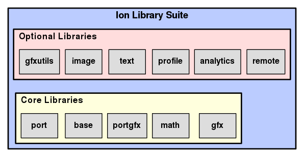
The core libraries are as follows:
port library in that it hides platform-dependent details behind a platform-independent API, but it is specifically for graphics functions. That is, it hides OpenGL implementation details that vary between platforms.The optional, higher-level libraries all depend on the core libraries. They are as follows:
This section provides a brief overview of the main Ion classes. It is not intended to be thorough; there is just enough information to make it easier to understand the examples in the rest of the guide.
One of the main ways Ion makes application development easier is by storing objects that represent graphics data. OpenGL is primarily an immediate mode library, meaning that commands issued through it are typically handled immediately by the hardware driver implementation. It also allows you to create certain run-time objects (such as vertex buffer objects and framebuffer objects) that represent the results of issuing those commands, but these objects are usually opaque to the caller and cannot be modified easily. Ion, on the other hand, is a retained mode library, meaning that it stores persistent run-time objects that represent the graphics data. Having these editable run-time objects makes it easier for you to examine the data and to make changes. The Ion objects are designed to be very thin wrappers around the actual OpenGL commands, so there is minimal overhead in using them.
The main classes involved in scene construction are as follows:
gfx::Attributes for use in a Shape.Once you have constructed a scene from one or more Nodes, you would probably like to render that scene onto the screen or into an image. These classes are used to do just that:
As a result of Ion's very general scene construction model, ownership of several types objects can be shared. Here are some examples:
To make these operations easier, most shareable objects in Ion are derived from base::Referent, which is an abstract base class that implements intrusive thread-safe reference counting. Each derived class has a corresponding typedef for a base::SharedPtr to itself. For example, the gfx::Shader class header defines gfx::ShaderPtr for convenience.
You may notice that many functions in Ion receive objects by const reference to smart pointers, as in this member function in the gfx::Node class:
This convention provides the advantage of using smart pointers for safety while avoiding unnecessary increments and decrements to the reference count just to pass parameters.
There is also an base::WeakReferentPtr for situations in which a weak pointer to a derived Referent class is needed.
std::shared_ptr in the future. However, if you use the typedefs, this change should not be very noticeable.
Time for the first example: drawing a rectangle on the screen (source file examples/rectangle.cc). This can be considered a "hello world" program for Ion. It creates a Node with a Shape that represents a yellow rectangle, along with the minimum state necessary to make the rectangle show up correctly.
Here are all the system and Ion headers used in the example:
Next we define a GlobalState struct, which encapsulates all of the state required by our FreeGLUT callbacks. We maintain an instance as a global variable, since there is no way to pass any user-defined data to the callbacks:
The BuildGraph() function creates and returns the gfx::Node that represents the rectangle. It starts by creating the (root) node. Note the use of gfx::NodePtr, which is a base::SharedPtr typedef:
It next uses the convenient gfxutils::BuildRectangleShape() function to create the Shape. Since we are not doing any complicated shading, we request just vertex positions to be created. (Other optional components are surface normals and texture coordinates.) We also set the size of the rectangle to 2x2 units so it ranges from -1 to 1 in X and Y. The Shape is added to the node:
The next step is to set up a gfx::StateTable with the state needed to render correctly. The window sizes are used to set up the viewport. We also set the clear color and depth-clear values, and enable depth test and back-face culling. (The latter two settings are not really needed for a single rectangle, but they are typically enabled for most 3D scenes). The StateTable is set in the node:
Next we need to set some uniform values in the node. You may notice that we did not specify a gfx::ShaderProgram for the node, meaning that Ion will use the default shader program when rendering its contents. The default program defines a vertex shader that just transforms each vertex by projection and modelview matrices and a fragment shader that just sets each fragment to a base color. The matrices and color are defined as uniform values in the global shader input registry, which is used by the default program. (Uniforms are specified by name; in this case, the three we care about are called "uProjectionMatrix", "uModelviewMatrix", and "uBaseColor".) Therefore, we first access the global registry, then use it to create gfx::Uniform values, which we then add to the node:
All that is left to do is return the node we built:
We define a FreeGLUT display function callback, which is called Render(). It just calls the gfx::Renderer::DrawScene() function, passing the node we created, then asks FreeGLUT to swap buffers:
The mainline for the program is mostly concerned with initializing and running FreeGLUT. The first chunk of Ion-specific code involves setting up the GlobalState:
After initializing FreeGLUT, we set up the gfx::Renderer in the GlobalState along with a gfx::GraphicsManager (which requires a FreeGLUT context for proper initialization):
Running this program should result in a dark blue 800x800 pixel window with a yellow rectangle in the middle. Pressing the escape button should cause the program to terminate.
We will modify this program in the subsequent sections to illustrate more Ion features.
In this example, we define and use a gfx::ShaderProgram with custom vertex and fragment shaders (source code in examples/shaders.cc) applied to the rectangle from the previous example. For brevity and clarity, we describe only the code differences from that example in this section.
The only additional header file we need is:
Next we specify the source code for the vertex and fragment shaders. We define the code here as C++ strings for simplicity, but writing the code this way can be tedious and error-prone. See the Development Tools section for better options.
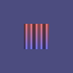
The example shaders apply a color gradient from the top to the bottom of the rectangle and also simulate diffuse illumination of a wavy surface from left to right. The vertex shader takes care of computing the color gradient (using two colors passed as uniforms) and passes that along with the object-space position to the fragment shader as varying variables (vColor and vPosition, respectively). It also takes care of transforming the object-space vertex position to clip space as usual:
Note that the gradient computation relies on the fact that the Y coordinates of the rectangle range from -1 to 1; this is done purely to keep the example simple.
The fragment shader simulates the wavy surface illumination by generating a surface normal based on a sine wave applied to the X coordinate of the rectangle (again, assumed to range from -1 to 1). The frequency of the wave is passed to the shader as a uniform:
You may notice that there are a few lines at the beginning of the fragment shader source that deal with precision. This code is unfortunately necessary at present if you plan to run your application on platforms that use OpenGL ES (typically mobile devices).
The next chunk of new code is in the BuildGraph() function. It creates a new gfx::ShaderInputRegistry for the custom shader program. A gfx::ShaderInputRegistry, as its name suggests, registers the inputs that will be used for a shader program. Each input is specified with its name, value type, and a description string. You may recall that in the preceding rectangle example we relied on the global shader input registry, which defines inputs used for the default shader program. We want to use some of those inputs (namely uProjectionMatrix and uModelviewMatrix) here as well, so we make sure to include the global registry in the new one, which makes those inputs accessible in our new registry. (Note that you can also use the gfx::ShaderInputRegistry::Include() function to include any registry in any other registry, as long as their inputs are distinct.) Then we add our three new uniforms to the registry:
Next we use a convenience function that constructs a gfx::Shader instance for each of the two shaders and installs them in a new gfx::ShaderProgram, which we then install in the node:
Finally, we add uniforms with reasonable values to the node. Note that we use our new registry to create the uniforms:
The rest of the code is identical to that in the previous example.
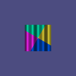
In this example, we modify the shaders from the previous example to apply a simple RGB texture to the rectangle instead of a color gradient, while still simulating the wavy illumination. We also demonstrate a little bit of matrix math to set up a texture matrix. The source code is in examples/texture.cc.
We need some additional header files for this example:
The vertex shader is similar to that in the previous example, except that it sets up varying texture coordinates (vTexCoords) instead of a color. The texture coordinates are modified by a matrix that is passed in as a uniform (uTextureMatrix):
The fragment shader uses the texture coordinates to access the correct fragment color from the texture, which is passed in as the uSampler uniform. (Note that the word "sampler" is used here in a GLSL sense to mean a way to sample values, as opposed to its upcoming use in an OpenGL sense, where it is an object that stores sampling parameters for a texture. Sorry for the confusion.) The rest of the shader is the same as before:
Next comes the code to set up the texture. First we define a function that creates and returns a 4x4 texture matrix to pass as the uTextureMatrix uniform. It rotates the texture by a specific angle around the center of the texture (which is .5 in both dimensions) using some of the handy Ion matrix utilities, solely for illustrative purposes:
Note that Ion matrices are defined so that the translation by (-.5, -5) is first, followed by the rotation, followed by the translation by (.5, .5). See the comments at the beginning of ion/math/transformutils.h for more details.
Next we define a function that builds and returns a gfx::Texture. Again, note the use of the gfx::TexturePtr smart pointer typedef as the return type:
First, we define the data for the pixels of the texture image. The image is a very simple 2x2 square of RGB pixels, for a total of 2x2x3 = 12 bytes. Since OpenGL defines images starting with the bottom row, the first 6 bytes specify the bottom row and the next 6 specify the top row:
While using an explicit array of pixel data is a convenient way to set up an image in an example, it is not really that useful in real-world applications. More likely, you will want to create the image using data read from a file; the image::ConvertFromExternalImageData() function can help with that. Also, you may find the base::ZipAssetManager class handy for embedding image data files and other assets directly in your application.
Next we create a gfx::Image that represents the texture image. The gfx::Image does not store the data directly. Instead, it uses a base::DataContainer, which provides a very thin wrapper to encapsulate the data. The container provides three flexible but well-defined mechanisms for specifying the wrapped data; see the class documentation for details. We use the simplest form, which tells the container to copy our data into an allocated chunk of memory. Once we have the base::DataContainer set up, we store it in the gfx::Image:
The true parameter passed to base::DataContainer::CreateAndCopy() tells the container that the data is wipeable, meaning that Ion can deallocate the memory once it is no longer needed. For a gfx::Image, this can happen as soon as an OpenGL texture object representing the texture that uses the image has been uploaded to the GPU. If you need to keep the data around for any reason, such as making modifications to it later on that cannot be done with gfx::Texture::SetSubImage(), do not set this flag to true.
Next we create a gfx::Sampler that indicates how the texture is to be applied:
Finally, we create a Texture using the image and sampler and return it:
The BuildGraph() function in this example is very similar to the one in the previous example. The first difference is that we have to tell the gfxutils::BuildRectangleShape() function that we require texture coordinates in addition to vertex positions:
Since we are using a different set of uniforms in our shaders, we no longer need to add the uTopColor and uBottomColor entries to the registry. Instead, we add the new uniforms used in the texture shaders:
We define a local variable holding the texture matrix:
Then we add uniforms to the node:
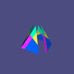
In the previous examples, we used the gfxutils::BuildRectangleShape() function to create a gfx::Shape to add to our node. If your application uses only basic shapes (such as rectangles, boxes, ellipsoids, cylinders) with only the predefined attributes (vertex positions, surface normals, and texture coordinates), feel free to use just this function and its kin. However, if you want to create more complex shapes, or if you need other types of attributes, you will need to write code to do that explicitly.
In this example, we modify the code from the previous example to explicitly create a simple pyramid shape. Each vertex of the pyramid has a position, a surface normal, and texture coordinates. For illustrative purposes, we also define an additional attribute for each vertex, a distance that is used to offset the vertex along the surface normal. For simplicity, we no longer apply the wavy illumination code. The source code is in examples/shape.cc.
As usual, we start with some additional header files:
However, we no longer need to include ion/gfxutils/shapeutils.h.
The vertex shader now uses the aNormal attribute from the global shader registry, so we declare that here. In addition, we create a custom attribute for the offset and a variable to pass the surface normal to the fragment shader. The new declarations are:
The new contents of the vertex shader are:
In the fragment shader, we no longer declare the uWaveFrequency variable, but now we need the normal:
The shader code is pretty straightforward:
Note that we use the absolute value of the dot product instead of clamping it, allowing the back faces to be illuminated. We also turn the intensity down a bit to make things look a little more subdued.
You may also have noticed that the normals are not transformed along with the vertex positions. To do so properly would require using the inverse transpose of the object-to-world-space matrix. For clarity and brevity, we avoid doing that here by just computing the lighting in object space.
Now to the code. We start by declaring a Vertex structure that contains all of the items to appear in each vertex. Note that the coordinates are declared as points and the normal as a vector; the Ion math library distinguishes between the two types to make operations safer and more self-documenting.
Next we define a function that builds and returns a gfx::BufferObject storing the vertex data for the pyramid. The pyramid consists of four triangles, one for each side. (We don't bother with the base; feel free to add it yourself.) We have to define distinct vertices for all of the sides, since each has different normals and texture coordinates, not to mention that we are going to offset them individually. The function header is:
We begin the function by defining the five coordinate points of the pyramid for convenience:
Next we declare a local variable to hold the 12 vertices of the pyramid (4 sides, each with 3 vertices) and set the positions manually:
Next we loop over the four faces to compute surface normals and set the texture coordinates. It would be fairly easy to just set the surface normals to known values, but this way lets us demonstrate how to use some of Ion's math library:
Next we set the offsets in each of the vertices. Their values don't matter too much, so we just do something stupid and easy:
Finally, we copy the vertex data into a base::DataContainer and set that in a gfx::BufferObject, which we then return:
The next function builds and returns a gfx::AttributeArray to represent the vertices stored in the gfx::BufferObject as attributes. Each gfx::Attribute in the array defines a binding of vertex data in a gfx::BufferObject to attribute inputs to a vertex shader. For example, we want to bind the position field for the vertices to the aVertex attribute input to the vertex shader. The gfxutils::BufferToAttributeBinder makes this process pretty easy - you just bind each of the registered attributes to the corresponding member field in a sample Vertex:
The next function builds and returns a gfx::IndexBuffer that stores vertex indices. We actually don't need to use indices for this very simple shape, as Ion will just use all of the vertices in order to create the pyramid triangles, but this shows how to create and use indices if you need to:
This code is similar to creating the vertex buffer, except that we copy a simple array of index values into the base::DataContainer. One other difference is the explicit call to gfx::BufferObject::AddSpec(), which was done for us in the vertex buffer case by the gfxutils::BufferToAttributeBinder class.
Creating the shape is relatively easy, now that we have the above functions:
All that is left to do is to update the BuildGraph() function to set up the pyramid shape. The first modification is to set the back-face culling state to false in the gfx::StateTable, which will allow all four pyramid faces to be displayed. Since this flag is disabled by default, we could instead just remove the line that sets it:
We no longer need to set up the uWaveFrequency uniform, but we do need to register the custom vertex attribute:
Adding the shape is easy:
This example also uses some Ion math utilities to set up the projection and modelview matrix values to create a different view:
All of the previous examples used a single gfx::Node containing a single gfx::Shape, but real-world applications typically need more than that. Ion provides the flexibility to structure your scenes to balance ease of construction and rendering performance.
For example, if you wish to render a collection of different primitive objects that all share the same state (shaders, uniform settings, global state), you can just add a gfx::Shape for each of them to a single gfx::Node. But if the objects do not share the same state, you need to use multiple gfx::Node instances. If you completely define the proper state for each node individually, you can just call gfx::Renderer::DrawScene() for each of them in your application's rendering loop. However, if the nodes share any common state, it will usually be more efficient to create a hierarchy in which the nodes can share some of the state. The example in this section shows how to do that (source code in examples/hierarchy.cc).
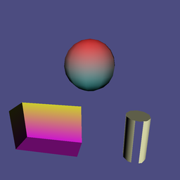
The scene is this example consists of three nodes, pictured in yellow in the below diagram. Node2 and Node3 are children of Node1, meaning that they will inherit state from it. All of the nodes have some state associated with them: state tables, shaders, and uniform values. Each node also has one shape (magenta) that illustrate the effects of the state present at the node.

Here are some rules about how state is inherited through a scene:
Node1 is used for both Node1 and Node2. The shader program in Node3 is used for Node3 and would also be used for any program-less children of Node3.Node1 will be present in all three nodes, whereas the state set by the table in Node2 will be present only for Node2.uModelviewMatrix uniform, which is defined in the global registry. This uniform accumulates its value by multiplying the inherited matrix and the new one. This feature is extremely important, as it allows you to easily create transformation hierarchies. (Note that you can define any new uniform to accumulate its values in any way you choose by specifying a gfx::ShaderInputRegistry::CombineFunction when you create a gfx::ShaderInputRegistry::UniformSpec.)The vertex shader for Node1 in the example applies a gradient from top to bottom (as in Example 2: Specifying Shaders) and passes the surface normal to the fragment shader:
Node1's fragment shader just applies the same basic lighting as before:
Node3's vertex shader just updates the position and passes the surface normal to the fragment shader. The fragment shader compares the surface normal and the uOpenDirection vector uniform and discards the fragment if they are similar enough:
The code contains a function to build each of the three nodes individually. Most of the code is similar to that of previous examples, so we will highlight only the important differences.
In the BuildNode1() function, we create a sphere shape using the gfxutils::BuildEllipsoidShape() function and add it to the node. Then we set up a gfx::StateTable and gfx::ShaderProgram as before. We need to add all four of the uniforms required by the shader program to the node:
In the BuildNode2() function, we create and add a box shape using gfxutils::BuildBoxShape() and also add a new StateTable that culls front faces instead of back faces. The rest of the state is inherited from Node1. Note that we use the default constructor for gfx::StateTable that does not take the window size parameters. They are not needed because we are not setting the viewport (or scissor box).
Then we set new values for the color and model-view uniforms. Note that we do not specify a new value for the uProjectionMatrix uniform, so that is inherited. Also note that the value for uModelviewMatrix is accumulated with the inherited value, which results in an extra translation applied to the box to position it at the lower left.
In BuildNode3(), we add a cylinder shape with gfxutils::BuildCylinderShape(). Then we set up and add a new registry and shader program to override the one in Node1:
We then set values for uniforms. Again, we do not have to set a value for the uProjectionMatrix uniform, as it is inherited from Node1, even though we are using a different shader. This is possible because the shaders in both Node1 and Node3 include the global registry, which defines that uniform.
Finally, we put all the pieces together in the BuildGraph() function:
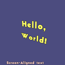
Earlier we called Example 1: Drawing a Rectangle the "hello world" program for Ion. This example shows how you can really show the words as text in your application. The source code is in examples/text.cc.
The Ion text library draws text as texture-mapped geometry. Specifically, it uses signed-distance field (SDF) textures to represent the character glyphs, along with shaders that display those glyphs nicely. The library makes it easy to display basic text and also makes it possible to create more complex representations. The main text classes are:
We need these additional header files:
The data for the font is stored in a header file created from a public-domain TrueType font. This is typically not the way you want to load font data, but it makes the example code simple and does not require any platform-specific file handling:
The CreateFont() function creates and returns a text::Font built from the data. We use a font size of 64 pixels, which is large enough to make the text look reasonably good:
The example builds two text nodes to display. The first one says "Hello, World!" on two lines. It is created by this function:
First, we set up a text::LayoutOptions instance that specifies how we want the text to be laid out. We set the size to be 0 units wide and 2 units high. This means that the text width will be computed proportionally to match the size-2 height. We specify that the text is to be aligned about the center in both dimensions, and the spacing between the lines is to be 1.5 times the maximum font glyph height. Then we build the text::Layout using the font, the desired string, and the options:
Then we set up a text::OutlineBuilder to build the text node. We specify some color and outlining options to make things look the way we want and return the resulting node:
The other text node in our example will be forced to be aligned with the screen. We set it up the same way, but with different size, alignment, and colors. We also set the target point to offset the text a little bit from the left side of the window:
In the BuildGraph() function we build a root node and add the two text nodes to it as children. The shader created by the text::OutlineBuilder requires the uViewportSize uniform (defined in the global registry) to be specified so that it can figure out how big font pixels are. We create a variable to store the window size:
And we use this when setting up the viewport in the state table:
And then we use it to set the uViewportSize uniform in the root node. We could store this uniform in both of the text nodes, where it is really needed, but this is more convenient and efficient:
Next we create a text::Font and text::DynamicFontImage:
We next build and add the text node for the "Hello, World!" text. We set up an arbitrary perspective view for this text:
Then we do the same for the screen-aligned text. Note that we set up an orthographic projection matrix to make the text (which is in the XY-plane) remain parallel to the screen.
In a real, interactive application, you may want to keep the text::Builder instance around to be able to make modifications to the text, such as changing its color or changing what string is displayed.
 1.8.6
1.8.6 
