k-ary n-fly Butterfly Topology Types
Overview
A k-ary n-fly butterfly topology type is a multistage logarithm network. It is implemented using n stages of identical routers, where k is the number of channels of a router that connect to the previous and/or to the next stage. For example, a 2-ary 3-fly butterfly topology has three stages composed of routers with two channels connect to the routers of the previous and/or the next stage (see Figure Butterfly_Topology_Example).
Each endpoint node and channel has an n-digit radix-k identifier, {dn−1, dn−2, ..., d0}. The first n−1 digits {dn−1, dn−2, ..., d1} of the identifier corresponds to the router that it is connected to. Each router node has an n−1-digit radix-k identifier. To distinguish nodes and channels from different stages, the stage number is appended to their identifier separated by a period. For example, for a 2-ary 4-fly butterfly network: 2.10102 is channel 1010 from stage 2. Butterfly_Ref_0
The connection between the stages is a permutation of the channel identifier. The connection of a channel from stage i-1 to stage i swaps digits dn−i and d0 of the channel identifier, with i >= 1 and i < n. For example, for a 2-ary 4-fly butterfly network: channel 910 of stage 1 [1.10012] is connected to router 4 [1.10012] of stage 1 and router 6 [2.11002] of stage 2. Butterfly_Ref_0
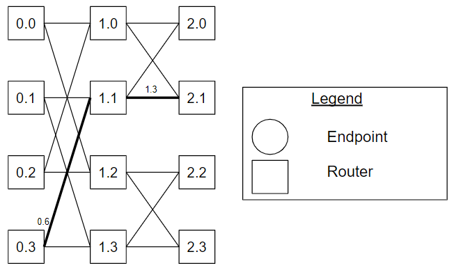
Figure Butterfly_Topology_Example. The router nodes of a 2-ary 3-fly butterfly topology.
Figure Butterfly_Topology_Example shows the router nodes of a 2-ary 3-fly butterfly topology. The routers are labelled with an S.I format where S is the stage identifier and I is the router identifier. For example, router 0.2 is router 2 from stage 0. Channel 0.6 is connected to router 3 [0.1102] of stage 0 and router 1 of stage 1 [1.0112], Channel 1.3 is connected to router 1 [1.0112] of stage 1 and to router 1 [1.0112] of stage 2.
Unidirectional Types
For the unidirectional type of the k-ary n-fly, there are endpoints connected to stage 0 and stage n-1. There are two configurations: 1) the endpoints connected to stage 0 send to the network, and the endpoints connected to stage n-1 receive from the network, and 2) the endpoints connected to stage 0 receive from the network, and the endpoints connected to stage n-1 send to the network. A unidirectional k-ary n-fly butterfly topology has at most kn endpoints connected to stage 0 and at most kn endpoints connected to stage n-1. Typically, the endpoints nodes connected to stage 0 and stage n-1 are the same nodes, resulting in an equal number of nodes connected to stage 0 and stage n-1. Moreover, the endpoints nodes are connected to stage 0 in the same order as stage n-1 (mirrored from the vertical cross section).
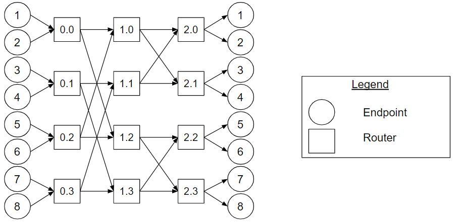
Figure Unidirectional_Butterfly_Topology_Example. A 2-ary 3-fly butterfly with the endpoints connected to stage 0 sending to the network, and the endpoints connected to stage 2 receiving from the network example.
Figure Unidirectional_Butterfly_Topology_Example shows a 2-ary 3-fly butterfly with the endpoints connected to stage 0 sending to the network, and the endpoints connected to stage 2 receiving from the network example.
Bidirectional Types
In the bidirectional type, there are endpoints connected to stage 0 or stage n-1. A bidirectional k-ary n-fly butterfly topology has at most kn endpoints connected to stage 0 or stage n-1. A bidirectional k-ary n-fly butterfly topology with the endpoints connected to stage n-1 is also referred to as the k-ary n-fly fat tree butterfly topology or k-ary n-tree butterfly fat tree topology Fat_Tree_Ref_0.
For context, minimal routing between a pair of nodes on a bidirectional k-ary n-tree can be accomplished by sending the message to one of the nearest common ancestors of both source and destination and from there to the destination. That is, each message experiences two phases, an ascending phase to get to a nearest common ancestor, followed by a descending phase. Fat_Tree_Ref_1
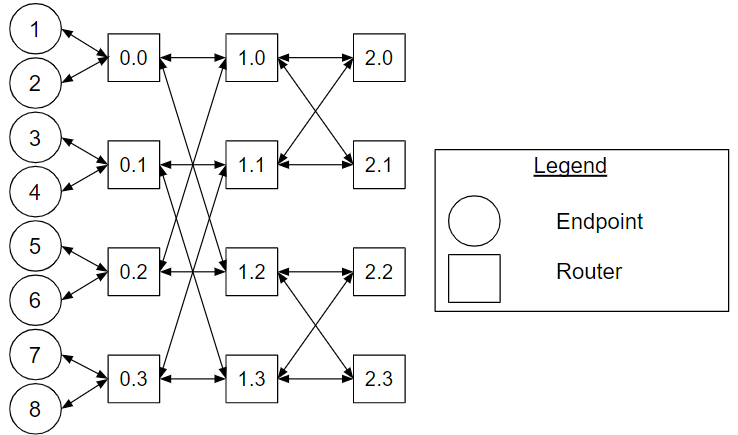
Figure Bidirectional_Butterfly_Topology_Example. A bidirectional 2-ary 3-fly butterfly with the endpoints connected to stage 0 example.
Figure Bidirectional_Butterfly_Topology_Example shows a bidirectional 2-ary 3-fly butterfly with the endpoints connected to stage 0 example.
Cheat Sheet
- k-ary n-flies are implemented by using n stages of identical routers, where k is the number of channels of a router that connect to the previous and/or to the next stage.
- For unidirectional k-ary n-fly, there are endpoints connected to stage 0 and stage n-1. The communication flows from stage 0 to stage n-1 or from stage n-1 to stage 0.
- For bidirectional k-ary n-fly, there are endpoints connected to stage 0 or stage n-1. The communication flows from stage 0 to stage n-1 and from stage n-1 to stage 0.
Variants
This section describes variants to the k-ary n-fly butterfly topology.
Flattened Butterfly
The flattened butterfly is derived by flattening the routers in each row of a conventional butterfly topology while maintaining the same inter-router connections. Butterfly_Ref_1
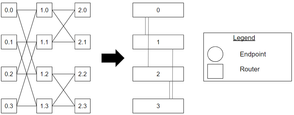
Figure Flattened_Butterfly_Topology_Example. An example of a 2-ary 3-fly butterfly and its corresponding flattened butterfly topology.
Figure Flattened_Butterfly_Topology_Example shows an example of a 2-ary 3-fly butterfly and its corresponding flattened butterfly topology. For each row, routers from stage 0, 1 and 2 are flattened into individual routers. For example, router 0.0, 1.0 and 2.0 are flattened into router 0.
Endpoint Connections
As mentioned, typically, for the unidirectional butterfly topology, the endpoints nodes are connected to stage 0 in the same order as stage n-1 (mirrored from the vertical cross section). However, different topologies are said to emerge by modifying the order of the endpoint nodes connected to the network. Such a change in connectivity may also change the routing algorithm. Ludovici et al present a Reduced Unidirectional Fat Tree derived from a k-ary n-fly topology. Fat_Tree_Ref_0
References
[Butterfly_Ref_0] William James Dally and Brian Patrick Towles. 2004. Principles and Practices of Interconnection Networks. Morgan Kaufmann Publishers Inc., San Francisco, CA, USA.
[Fat_Tree_Ref_0] D. Ludovici et al., "Assessing fat-tree topologies for regular network-on-chip design under nanoscale technology constraints," 2009 Design, Automation & Test in Europe Conference & Exhibition, Nice, 2009, pp. 562-565, doi: 10.1109/DATE.2009.5090727.
[Fat_Tree_Ref_1] F. Petrini and M. Vanneschi, "k-ary n-trees: high performance networks for massively parallel architectures," Proceedings 11th International Parallel Processing Symposium, Genva, Switzerland, 1997, pp. 87-93, doi: 10.1109/IPPS.1997.580853.
[Butterfly_Ref_1] J. Kim, J. Balfour and W. Dally, "Flattened Butterfly Topology for On-Chip Networks," 40th Annual IEEE/ACM International Symposium on Microarchitecture (MICRO 2007), Chicago, IL, 2007, pp. 172-182, doi: 10.1109/MICRO.2007.29.